Solid Rocket Motor
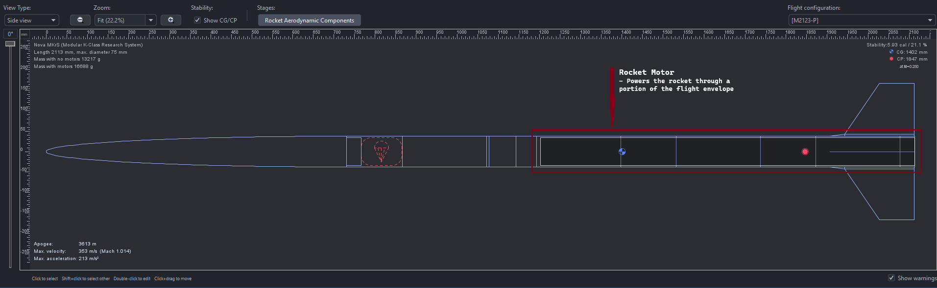
A solid rocket motor (or solid propellant motor) is a type of propulsion motor used in amateur rocketry and professional aerospace to provide thrust to an object. In amateur rocketry, solid rocket motors are often the only safe, legal, or feasible option for powering the rocket, due to the challenges associated with developing other types of thrusters, such as liquid propellant engines and more exotic air-independent propulsion methods.
Solid rocket motors consist of various components, each crucial to ensuring proper functioning and preventing catastrophic failure modes and RUDs (Rapid Unscheduled Disassembly) of the motor and/or its surroundings.
Rocket Motor Components
-
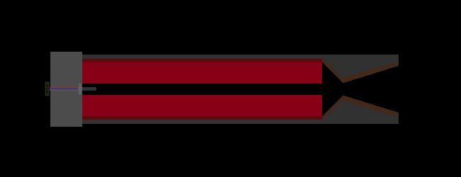
Forward Closure & Insulation ▼
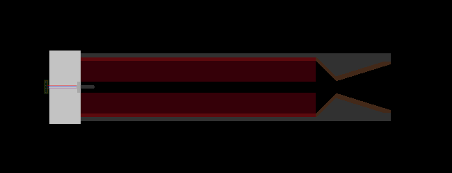
Function & Design:
The forward closure serves as the uppermost seal of the motor casing, encapsulating the propellant grain and housing the ignition mechanism. Its hemispherical or ogive geometry minimizes stress concentrations under internal pressure.
Materials & Manufacturing:
Constructed from high-strength aluminum alloys (e.g., 6061-T6) or maraging steel, the closure is typically CNC-machined or forged to achieve precise dimensional tolerances (±0.05 mm). These metals balance tensile strength (≥400 MPa for aluminum) with weight efficiency.
Tolerances & Integration:
Radial bolt holes, machined to ±0.1 mm concentricity, secure the closure to the motor casing via high-grade steel bolts (ISO 10.9 class). A Viton® O-ring, seated in a machined groove, ensures pressure sealing (tested to 1.5× operational pressure). The interface must resist shear stresses induced by axial acceleration and vibration.
-
Motor Ignition Mechanisms ▼
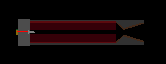
Design Principles:
The ignition system employs a pyrogen or electric match to initiate combustion. A nichrome wire bridge, embedded in a pyrotechnic paste (e.g., potassium nitrate-sucrose), is energized by a 12–24V circuit, generating sufficient heat (≥800°C) to ignite the primary propellant.
Manufacturing & Integration:
Igniters are hand-cast or automated-dispensed into phenolic or plastic housings. Critical tolerances include wire resistance (±0.2 Ω) and pyrogen mass consistency (±5%). The assembly is thread-sealed into the forward closure or bonded via high-temperature epoxy, ensuring gas-tight ignition transmission.
-
Motor Casing Layers ▼
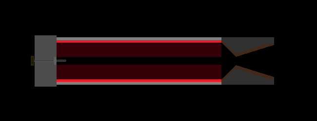
Structure & Materials:
The motor casing comprises an outer metallic shell (aluminum 6061/7075 or 4130 steel) lined with an ablative insulation layer (e.g., EPDM rubber or cellulose-fiber-reinforced phenolic). The casing is manufactured via spin-forming or extrusion, achieving wall thickness uniformity within ±0.2 mm.
Insulation Layer:
A 2–5 mm cardboard or silica-filled phenolic resin layer is bonded to the casing interior via epoxy. This insulation pyrolyzes during combustion, absorbing heat flux (up to 3 MW/m²) and protecting the metal from temperatures exceeding 300°C.
Closure Integration:
The forward and aft closures are bolted to the casing with radial patterns of 6–12 M8–M12 bolts, preloaded to 70% of yield strength. Shear pins may supplement alignment, ensuring uniform compression of O-rings under dynamic loads.
-
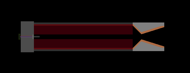
Propellant Formulation & Grain Design ▼
Composition:
Solid propellants typically use ammonium perchlorate composite (APCP) or double-base formulations. APCP combines ammonium perchlorate (oxidizer, 68–72%), aluminum powder (fuel, 16–20%), and HTPB binder (10–12%), cured at 60°C for 48 hours.
Grain Geometry:
The grain’s internal geometry (e.g., star, cylindrical, or finocyl) governs burn surface evolution and thrust profile. Tolerances for core geometry are held to ±0.5 mm to prevent erosive burning anomalies.
Bonding to Casing:
The propellant is directly cast into the insulated casing, with a bonding agent (e.g., epoxy primer) preventing debonding under thermal cycling. Mechanical mandrels ensure concentricity (<0.3 mm radial deviation).
-
Motor Nozzle Design & Engineering ▼
Materials & Construction:
Nozzles employ a multi-material approach:
-
Throat Insert: Graphite or silicon carbide, machined to ±0.1 mm throat diameter, withstands stagnation temperatures >2500°C.
-
Exit Cone: Carbon-phenolic (resin-impregnated carbon cloth) or ablative phenolics (e.g., MX-4926), layered and cured under 100 psi pressure.
-
Housing: Aluminum or steel, threaded or bolted to the aft closure.
-
Additional Design Considerations